Transform medical device design using NX software
Hundreds of millions of people through the world are dealing with diabetes. The expanding need for diabetes management is pushing innovation forward within the insulin pump market. An insulin pump demonstrates the complexities between the electronics and mechanical functionality of the device. These innerworkings are common within medical devices. Disjointed mechanical and electrical design systems create issues with lost information and limited traceability and visibility.
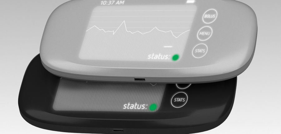
However, using CAD software should not inhibit manufacturers from building life-saving devices. To demonstrate how simple it is to bring products to life, a Siemens Digital Industries Software intern created an insulin pump using our most advanced design tools in NX. Let’s explore the design process and how NX helped our intern design the insulin pump.
Case design using NX
First, the insulin pump began with a primitive shape and then was manipulated to morph the shape as needed. Within this environment, methods of pushing and pulling points were utilized to manipulate and intentionally shape surfaces in limitless ways. Using symmetric modeling tools was an effective way to accelerate the modeling process while also developing a realistic form.
Once the form was in the desired shape, the form was refined with NX Realize Shape™ surfacing tools. The edges were made sharper or smoothers. The edge blend tool smoothed out creases and created a more finished surface. The continuity tool provided the ability to sharpen and smooth the form.
Next, additional surfaces and bodies were used to trim the main body of the insulin pump. Reinserting the design into NX Realize Shape mode, a rectangle was used to trim the original body to create a specific surface. Before continuing on with the building stage, the current design was evaluated using surface analysis tools, such as curvature, reflection and section analysis to see how the form appears with lighting.
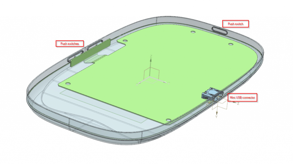
After the rendering and surface analysis, the form was split using the split body tool and the halves were shelled. At this stage, any separate components of the design were added, such as buttons and switches.
ECAD and printed circuit board design
Once the shape of the pump was designed and components were finalized, the shelled body was used as a reference to develop a printed circuit board (PCB). Then, the product was tested with simulation and analyzed for any issues.

“NX enabled me to design this insulin pump remote by equipping me with a wide array of surfacing tools for refining the form along with the ability to complete multiple stage of the design process within the same software. By utilizing the visualization capabilities, I was able to analyze the surfacing throughout the design process and bring the product to life.”
Siemens Digital Industries Software Intern
If an intern can use NX, imagine what your seasoned engineers and designers could do.

Don’t hesitate to contact Thanh for advice on automation solutions for CAD / CAM / CAE / PLM / ERP / IT systems exclusively for SMEs.
Luu Phan Thanh (Tyler) Solutions Consultant at PLM Ecosystem Mobile +84 976 099 099
Web www.plmes.io Email tyler.luu@plmes.io
