Design with a Purpose: Introduction into Lattice Structures
We are living in an industrial revolution full of technological advancements. The world is changing by designing for sustainability and environmental impact. This revolution is ubiquitous in every industry, especially in automotive, aerospace, energy, and biomedical fields. While these industries contain different markets, products, and innovations, they all have one characteristic: manufacturing. The key to designing for purpose is to ensure sustainable manufacturing processes. Here at Siemens DISW, we empower users to advance projects by providing innovative tools to modernize their solutions and processes. Our software is at the forefront of sustainable innovation by developing a full additive manufacturing lifecycle workflow that can turn your ideas into reality in record times. This is possible with the use of upgraded NX design for additive manufacturing features, integration of MultiMechanics, enhanced simulations, and continued development of HEEDS (a design space exploration and optimization software). This article is the first of five that will highlight the full lifecycle workflow that Siemens DISW equips you with to design for purpose.
The first tool that empowers users is the newly enhanced NX Lattice Structure Design capabilities. Located in NX Design for Additive, this is an optional add-on module to NX that enables users to streamline the creation of complex lattice structures. Inspired by naturally occurring crystalline formations, lattices are a repeating arrangement of two or three-dimensional microstructures. These micro-structures contain a network containing beams, also called struts, and nodes, or balls. With the increase in additive manufacturing technologies, lattice structure techniques are growing in functionality and popularity. The tunable nature of lattices allows engineers to refine designs to match their applications. Integrating lattice in design allows for significant mass reduction, reducing the cost associated with needed resources, tooling procedures, shipping, and energy consumption. While additive manufacturing does decrease material waste by eliminating the need for additional tooling byproducts, the incorporation of lattice structures in design allows for further material conservation because of the lattices’ porosity. Designs are engineered for performance due to lattices having low stiffnesses and the ability to withstand and recover large strains. They protect products by aiding in absorbing impact energy and vibrations. The strength-to-weight ratio can be significantly enhanced. The structural integrity/fatigue life can be improved through virtual simulation and material testing of the lattice designs using Multimechanics and HEEDs, which will be explored in future articles.
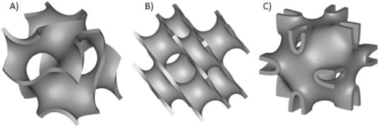
Knowing the benefits that lattice techniques add to designs, Siemens NX equips users with three command sets of lattice structures: graph-based structures, body lattice structures, and triply periodic minimal surface structures. Each serves a unique purpose and possesses individual benefits. Lattice structures with unit cells based on triply periodic minimal surfaces (TPMS) are free of self-intersections and have topologies generated by mathematical equations. Examples of such structures include the Schoen gyroid, Schwarz diamond, and Neovius. TPMS structures are often self-supporting and provide great energy absorption. A few examples of TPMS structures can be seen below in Figure 1.

Body lattice structures allow users to create their own three-dimensional repeating pattern within a part. With endless possibilities and combinations, this option allows for design flexibility and easy customization. An example of body lattice structures can be seen below in Figure 2.

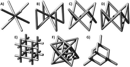
Graph-based structures are the most thought of the type of lattice, consisting of tessellating ball and strut configurations. There are many cell arrangements, and each holds exclusive structural and thermal properties to innovate design. A few examples of graph-based structures can be seen below, in Figure 3.

With the knowledge of what lattice structures are and their ability to radicalize sustainable designs, we will look at an example of how lattice structures can be implemented in manufacturing to better the processes used to create parts in every industry. The part shown is an injection die mold that was designed using traditional machining practices. In the demonstration, this part will be redesigned for an additive manufacturing approach. The changes applied to allow for an eco-friendly industrial tool designed and manufactured in less time, with reduced part weight and better structural properties for an increased lifetime. Part preparation in this demonstration utilizes NX capabilities such as synchronous and implicit modeling functionalities that design and redesign parts a breeze. Implicit modeling allows for more robust part designs in less time than traditional modeling. Tools. With implicit modeling capabilities, shelling this part took minutes rather than hours.

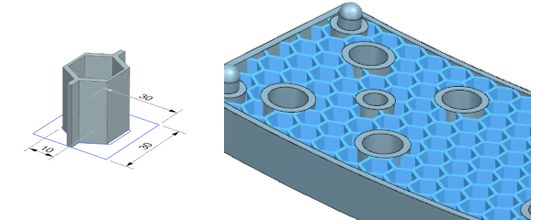
As you’re about to see in the demonstration, two types of lattices will be applied to the part’s internal cavity, shown in Figure 3. The first lattice chosen is a Quad-Diametral (BCC) structure with an edge length of 6 mm and a rod length of 1 mm. Balls were not incorporated but can be added to intersecting struts to increase structural properties. Orientation is kept unchanged for best build print setup, and disconnected lattice portions are removed as needed. What used to take months to design now takes minutes with these three simple steps. The second type of lattice applied is the diamond TPMS structure. This lattice is applied for comparison to the BCC graph lattice structure. After comparing the two, the BCC lattice is applied to the open cavity; it is united using Boolean commands in the NX home modeling menu.

Now that you’ve seen how simple the creation of advanced lattice structures is in NX, you’ll be able to design for purpose and modernize manufacturing processes. Don’t trust me yet? Then stay tuned for the next Design for Purpose article, where I will dive into the following phase of our beginning to end solution by applying the lattice’s structural properties on a micro-level to determine how and where this design will fail. How is this possible? You may be thinking that magic is the explanation, but in fact, it is the other M word – MultiMechanics. In the subsequent article, I will introduce NX Multimechanics capabilities and go in-depth into the workflow and benefits that Multimechanics has over traditional material testing options.
References
(01) Tobias Maconachie, Martin Leary, Bill Lozanovski, Xuezhe Zhang, Ma Qian, Omar Faruque, Milan Brandt, SLM lattice structures: Properties, performance, applications and challenges, Materials & Design, Volume 183, 2019, 108137, ISSN 0264-1275, https://doi.org/10.1016/j.matdes.2019.108137.
(https://www.sciencedirect.com/science/article/pii/S0264127519305751)

Don’t hesitate to contact Thanh for advice on automation solutions for CAD / CAM / CAE / PLM / ERP / IT systems exclusively for SMEs.
Luu Phan Thanh (Tyler) Solutions Consultant at PLM Ecosystem Mobile +84 976 099 099
Web www.plmes.io Email tyler.luu@plmes.io
