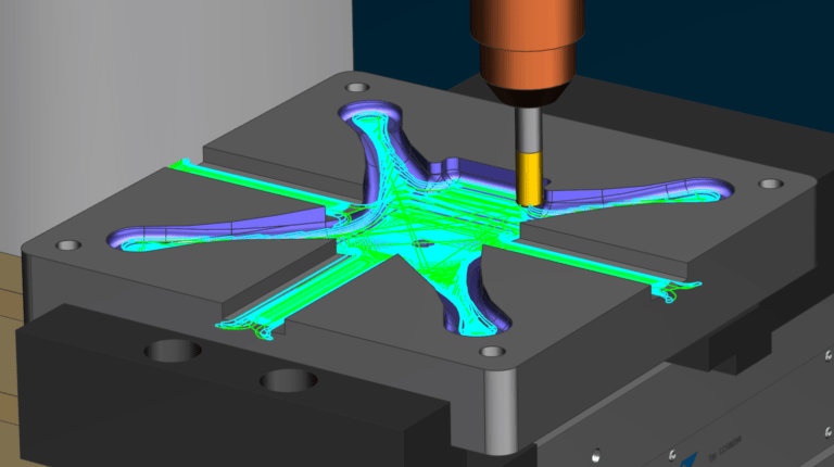
Moving into Metal: CNC Programming of the Quadcopter’s Molds
In this post, we’ll continue our tour through the Digital Machine Shop as the mold for the plastic top of a quadcopter moves from design into manufacturing.
My name is Lars Okkels, and I am a CAM Consultant here at Siemens Digital Industries Software. As a specialist in the CNC programming of molds, my role was to develop the machining processes used to manufacture the mold for this part. (This mold was designed by Himanshu Iyer using NX Mold Design. He explained his process here.)
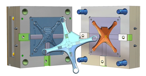 Mold for the quadcopter top cover designed in NX CAD Mold Wizard
This was not a highly complex mold, but even so, it required 7 mold plates, 1 core insert, 1 cavity insert, and 16 electrodes. I’ll focus here on the core and cavity inserts, the mold plates, and the ribs on the underside of the part. The ribs are the area that necessitated die sink EDM.
In general, my main goal in the CNC programming of molds is to maximize machining efficiency. This guided my work on the quadcopter part’s mold, and I’ll explain below how I used technologies within NX CAM to achieve it. NX is much more than a CAM software – it’s a complete part manufacturing solution, with advanced functionality such as simulation and process wizards that allowed me to work efficiently and optimize the manufacturing processes involved here.
In addition to machine efficiency, my other critical goal, as a mold maker, for this project is producing a very smooth surface on the cavity. It would form the top of the plastic part – the visible area that would give people their overall impression of the quadcopter. Also, I wanted to avoid mistakes in production that would slow the project, such as finding out that tools were too short, for instance, or that clamping needed to be moved. NX CAM helped me address these considerations as well.
The digital thread continues.
Similar to how mold design began with CAD data, the starting point for me was also digital, i.e., Himanshu’s NX file of the mold design. It was nice knowing that he had used the Digital Twin approach and the technologies available to him in NX Mold Design to ensure that the part was actually moldable. He also made sure that the mold was optimized for performance, for example, by use of features such as conformal cooling channels to shorten the cooling time.
I also used the Digital Twin approach, which for CNC programming of molds means working in the complete machine setup and having connectivity to the original model design. This helps me program any job faster and simulate operations to optimize them before sending them to the shop floor. The cavity insert offers a good example of this.
Cavity programming
With inserts, you’re typically making only one or two parts, so it’s important to get them right the first time. Machining, particularly roughing, of hard materials used for molds can take a long time if you use conventional machining methods. I used NX’s Adaptive Milling, high-speed machining (HSM) method that enables deep cuts at high cutting rates to speed up the process. It can shorten roughing cycle of the toughest materials by 60%.
As I mentioned earlier, a key goal in milling the cavity was to achieve a super smooth surface. This was obvious to me since the top of the quadcopter is a visible part. But also, the mold designer conveyed the desired surface quality and tolerances by using the product and manufacturing information (PMI) added to the 3D model of this mold.
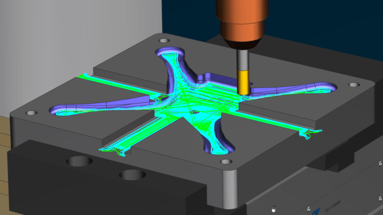
Surface quality involves the interplay of many variables, including cutting strategies, speeds, feeds, the choice of cutting tools, etc. Therefore, I used my previous experience in the CNC programming of molds and the advanced toolpath technologies in NX in the process. For instance, to follow the natural shapes of the mold shape, I used the Guiding Curves finishing that generates a smooth-flowing toolpath that results in an excellent surface finish.
The G code-driven simulation functionality within NX CAM is a great way to validate the machining process. On my screen, I could observe material removal, machine moves, and so on, and quickly make changes to optimize surface quality.
Core programming
The strengthening ribs added by the designer to the underside of the part affected how I programmed the milling of the core. The sharp angles created by the ribs necessitated the use of die sink EDM. But before using EDM, I needed to rough that area as quickly as possible without machining the rib details. NX CAM has a great feature called Geometry Wave Linker that allowed me to make changes to the geometry of the core insert without affecting the CAD model while maintaining associativity to the original design. In addition, I simplified the geometry of the rib area to optimize the toolpath, which helps me shorten the machining time.
 NX’s Synchronous Technology enables engineers to edit the part model directly and prepare it for NC programming, including closing holes and gaps, offsetting faces, and resizing part features.
Electrodes are used for the die sink EDM process. This core needed 16 electrodes, but some molds require hundreds, so automating electrode programming is essential. Siemens provides this through the NX Electrode Design Wizard. It guided me through a step-by-step workflow to design the electrodes. It lets you specify things like extension height, draft angle, material, and spark gaps, combined with various Synchronous Modeling functions, that allowed me to define the electrode geometry (offsetting faces or adding blends) to allow for a better EDM process.
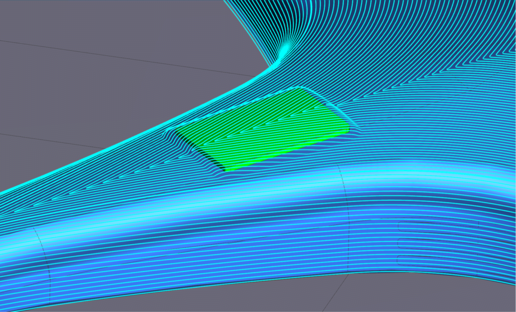
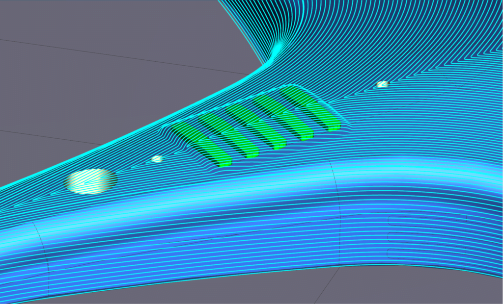 The smooth-flowing Guiding Curves operation in NX CAM is an ideal cutting method for high-speed finishing.
Mold plate programming
Mold plates are the parts in the mold assembly that hold the core and cavity inserts in place. A mold typically has seven or eight plates characterized by many pockets, holes, slots, etc. Although these features are not complex, programming them can take a lot of time and manual selections. NX CAM provides the capability to automate the programming of mold plates. Using this automation functionality, some of our customers have reduced programming time for mold plates by more than 90 percent.
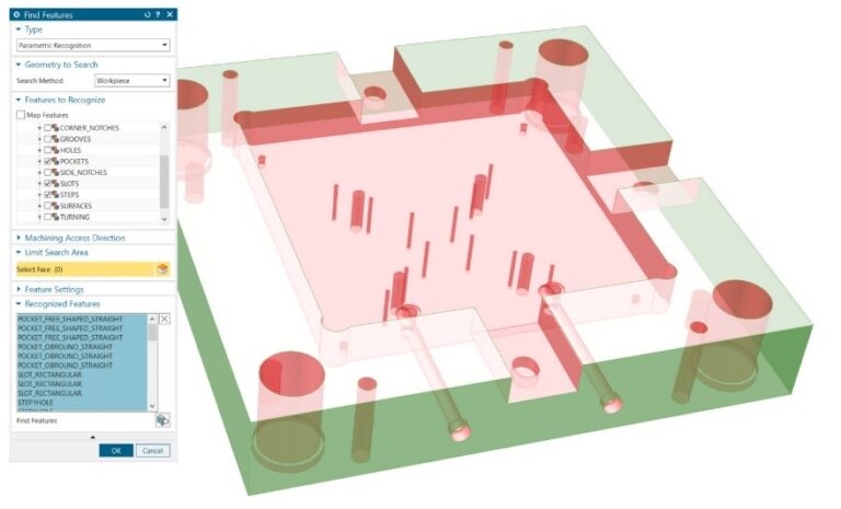 With Feature-based machining (FBM) in NX CAM, you can automatically create optimized machine programs directly from part design models. FBM automatically recognizes and programs a wide range of machining feature types, such as pockets, holes, and slots
The automation helps you speed up the programming of the plates so you can dedicate your time to the more complicated parts like the core and cavity inserts. For the quadcopter mold, I took advantage of two capabilities of NX CAM to accelerate the task: feature-based machining (FBM) and the ability to use the PMI information from the original CAD model to automate the process further.
Feature-based machining in NX CAM is very powerful. In this case, it started by analyzing the plate geometry and identifying features such as holes (simple or compound), pockets, notches, slots, etc. The basic functionality out-of-the-box can recognize more than 70 features, but you can also define your own. Because these plates are often machined from multiple sides, you can choose to recognize features from specific directions or all directions. I opted to have it recognize features from both top and bottom machining directions.
Once the features were identified, NX CAM automatically programmed the toolpaths, using tolerance data included in the PMI to ensure that required tolerances would be held. It’s swift. For example, it took me less than five minutes to program the ejector plate, taking hours to program using conventional methods. In addition to greatly reducing programming time, another benefit of feature-based machining is that it ensures a consistent machining process by all levels of programmers.
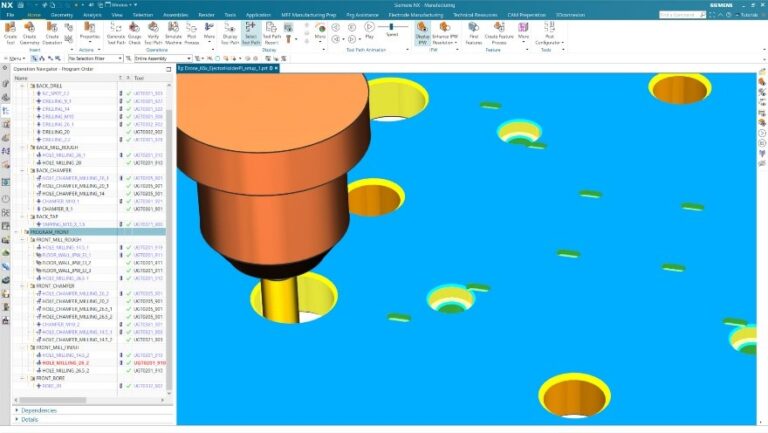 Programmers can create a complete machining process for mold plates, like the one shown here, in a matter of minutes using FBM in NX CAM. It automates programming and standardizes processes, ensuring the use of the company’s best practices.
Machining process validation
Since much of my work aims to maximize machining efficiency, and one aspect of that involves reducing downtime, I appreciate the G-code-driven simulation functionality in NX CAM.
The simulation capability is a perfect example of how a Digital Twin replicates the real world. Siemens has relationships with all major machine tool manufacturers, and they have worked with us to build exact virtual replicas of their machines. These replicas are incorporated into the simulation functionality of NX CAM. Working with a precise digital copy of the milling machine gave me confidence that I was getting smooth, efficient tool motions and consistent tool path quality and that the CNC programs I would be sent to the shop floor were error-free. For example, using the integrated simulation, I ensured that we didn’t find other problems on the shop floor, such as tools that were too short or clamping that weren’t right.
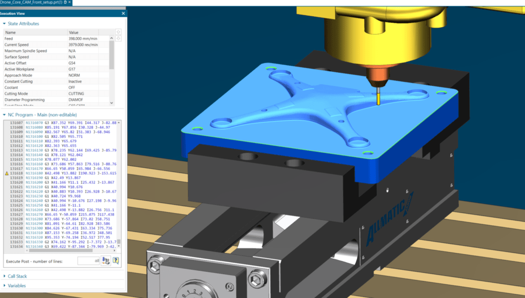 A key NX CAM advantage facilitates integrated simulation and verification of the NC programs (or G-code), enabling programmers to check tool paths within the NC programming session.
Without this type of simulation, a machine operator could have performed a dry run on the actual machine, but this would have taken that machine out of operation, which can negatively impact your productivity.
Postprocessing & shop floor docs
The postprocessing involves generating the NC program (or G code) to drive the CNC machines on the shop floor. It is one of the critical steps as you transition from planning to production. You need to “translate” the toolpaths you created into a code for your specific controller-machine configuration. As a user of NX CAM, I have access to more than 1,000 postprocessors stored in the cloud-based Post Hub. I didn’t need to leave NX to access the online library, and it was straightforward to use. I selected my machine and controller, and Post Hub showed me the applicable postprocessors. I generated the desired NC program using the postprocessor that I selected. But if I needed to modify the output, I could have used Post Configurator, which is very simple to use.
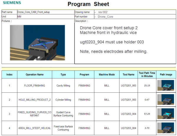
In addition to G code, I generated complete documentation for the shop floor, including tooling data and work instructions. All of this output was also generated automatically with NX CAM.
The advanced machining methods discussed in this blog helps mold makers shorten machining time and improve surface finish quality. At the same time, the latest toolpath technologies help manufacturers extend tool life and improve machine performance, reducing production costs. The digitally validated toolpaths eliminate the need for physical test cuts to increase machine uptime and virtually eliminate scrap.
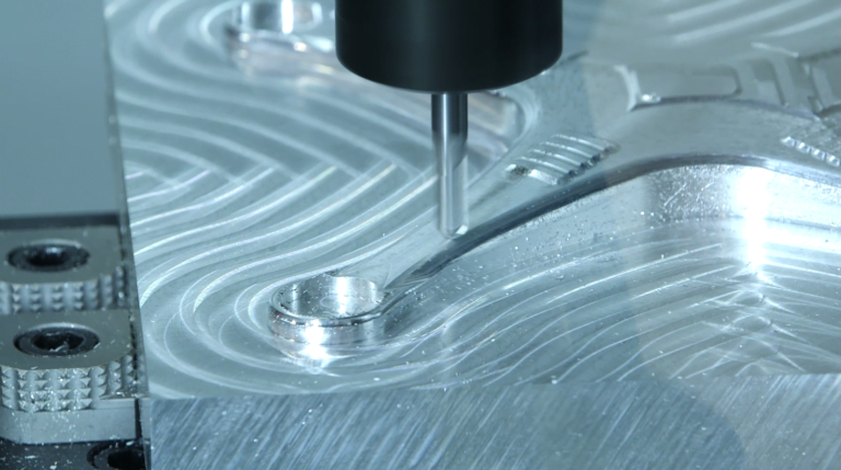 The advanced toolpath technologies in NX CAM enable shorter machining time and better surface finish, accelerating the manufacturing of high-quality molds.
The next post will cover another important step in the quadcopter part’s development – additive manufacturing, which was used to create the conformational cooling channels on the mold.
If you’d like to learn more about my world, check out my blog post about mold manufacturing.
Read the first blog in our digital machine shop series here and catch up on the previous blog here.

Don’t hesitate to contact Thanh for advice on automation solutions for CAD / CAM / CAE / PLM / ERP / IT systems exclusively for SMEs.
Luu Phan Thanh (Tyler) Solutions Consultant at PLM Ecosystem Mobile +84 976 099 099
Web www.plmes.io Email tyler.luu@plmes.io
