3D print distortion? Iterative model compensation can help | Simcenter
Print not what you expected
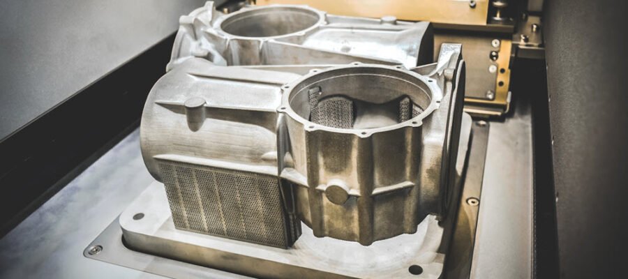
3D printing, otherwise known as additive manufacturing in the industrial world, has proven to be a great way to manufacture innovative parts that you wouldn’t be able to build by traditional manufacturing methods. Manufacturers in industries such as gas turbines, automotive and industrial machinery are beginning to use additive manufacturing to produce high-precision metal components.
If you’re new to 3D printing, you might think that all you need to do is design your part in CAD, hit the print button, and voilà – there’s your part! But when you go to assemble your part with the rest of your highly engineered machine, you’ll suddenly realize the part doesn’t fit or perform because the 3D printed part is distorted.
Now what do you do?
You could manually measure the distorted part with calipers to compare it with your nominal geometry dimensions. Then you could go back to your CAD model and manually modify the part in the opposite direction of the distortion in hopes that will result in a perfectly printed part. Re-print the part, re-measure, and re-adjust the CAD model.
Lather, rinse and repeat.
That’s not an efficient way to get to the right print that you need, and printing a lot of waste parts is expensive.
Simulate the build process
Additive manufacturing build processes apply lots of heat directly to the model in a specific location on your part. That part then cools down, but then heats back up when the next layer is applied. As you have learned since a young age, heat causes material to expand and material contracts as it cools. The localized repetitive heating and cooling causes the part to deform and distort during the 3D printing process.
Simcenter 3D can help you simulate the additive manufacturing build process for your part. Simcenter 3D will perform thermal-mechanical multiphysics simulation of the entire build process to predict distortions and defects before you ever print a part.


Iterative model compensation
Now that you know how the part will distort, you can also use Simcenter 3D to automatically calculate what the compensated geometry should be so that you can get your first print right. The latest release of Simcenter 3D includes a new iterative calculation of the distortion solution to determine an optimal, more accurate pre-deformation for a specimen. This new method will move all nodes independently to create a compensated geometry. When printing this compensated geometry will then result in a final printed part that matches the nominal geometry you modeled in CAD.
Example iterative model compensation workflow in Simcenter 3D
The following image shows a general example of the workflow for performing model compensation for a 3D printed part:

Step 1) This shows the nominal geometry for the burner head as defined in CAD
Step 2) The next step is to use Simcenter 3D Additive Manufacturing to simulate the build process. This simulation takes thermal-mechanical multiphysics into account to determine the final distortion and deformation of the final printed part.
Step 3) Considering the distortion calculated from the build process simulation, step 3 is then the first pass at determining the compensation. This is showing what the initial compensation would be – essentially taking the reverse of the the initial distortion that was calculated.
Step 4.i) Simcenter 3D re-simulates the build using the initial “compensated” geometry, and we are showing the new distortion compared to the original “nominal” geometry. You can see there is still distortion at the blade tips – now in the opposite direction.
Step 4.ii) Simcenter 3D will continue to automatically iterate the compensation process, optimize and compare with the nominal geometry. This step shows the results after 5 iterations, where we now have a compensated part that will very closely match the nominal geometry after a build.
Get your first 3D print right
By using Simcenter 3D for additive manufacturing build process simulation, you can more easily learn how your part will print without having to waste material, time and cost into doing many trial and error builds. With iterative model compensation, you can rapidly determine your geometry compensation so that you can ensure your print will match the right geometry on the first try.
For more information on additive manufacturing simulation and Simcenter 3D
- What’s New in Simcenter 3D 2021.2?
- Simcenter 3D solution guide
- Additive Manufacturing
- Free Trial: Try Simcenter 3D online today for 30-days
- Contact us for more information

Don’t hesitate to contact Thanh for advice on automation solutions for CAD / CAM / CAE / PLM / ERP / IT systems exclusively for SMEs.
Luu Phan Thanh (Tyler) Solutions Consultant at PLM Ecosystem Mobile +84 976 099 099
Web www.plmes.io Email tyler.luu@plmes.io
