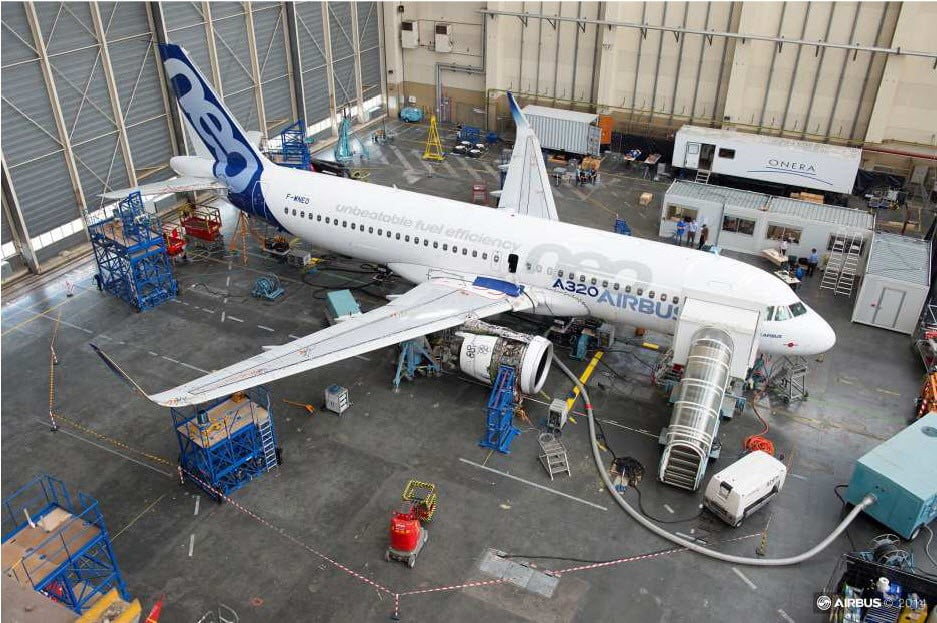
A ground vibration test (GVT) aims to characterize an aircraft’s structural resonances experimentally. This is an important step in the aircraft certification process. It helps validate the models used for aeroelastic prediction and verify that no flutter occurs within the flight envelope.
Challenges in aircraft instrumentation during GVT
Instrumenting the aircraft for this test can be a tedious task. Hundreds of sensors – single- and multi-axis accelerometers – must be attached to the aircraft structure to measure the vibration response to the shaker excitation. These sensors must be placed at well-defined locations on the structure and positioned with the right orientation to allow accurate measurements, which requires care and time. They should be properly glued to the structure to avoid detaching during the test, which would lead to inaccurate results or delays in the measurement campaign.
Modern data acquisition systems provide advanced capabilities for accelerating the instrumentation phase and for verifying that the measurement set-up is correct. But still, engineering teams involved in the GVT are often under pressure to deliver results as quickly as possible to minimize delays in the aircraft program. And the measurement task might be quite complex, involving multiple aircraft configurations to be tested and requiring to capture all relevant phenomena affecting the aircraft structural response. For instance, characterizing non-linearities in the aircraft structure might require detailed investigations and extra instrumentation. This challenges the GVT teams to deliver results that are complete, accurate, and within time.

Looking for more flexible measurement techniques
Although accelerometers have been the most used sensors in past GVT campaigns, they only provide discrete data, involve lengthy instrumentation, and require careful cabling management. One may wonder if a contactless measurement technique could be used to solve these challenges and complement accelerometer-based measurements.

Getting deeper insights into aircraft structural dynamics with Digital Image Correlation
Imagine using your camera to film the GVT test and directly obtain the aircraft structure’s vibration out of this movie. Well, this is pretty much what the Digital Image Correlation technique (DIC) allows to do! This contactless measurement technique relies on digital cameras and provides full-field vibration data by processing the acquired images’ sequence. Originally used for material testing and quasi-static measurements, the technique was further applied to dynamic measurements and modal testing. As opposed to accelerometers or vibrometer measurements providing discrete results, this DIC technique directly provides full-field displacement information.
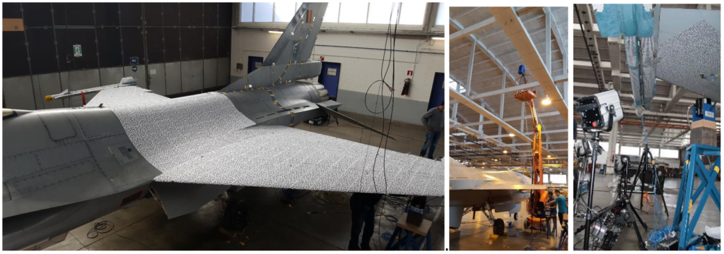
Moreover, the camera set-up time is fairly quick, and the calibration process very easy. A speckle pattern must be applied to the structure to ensure that the cameras’ images can be processed and provide displacement information. Multiple synchronized cameras can be used to cover large measurement surfaces. This makes it possible to use the DIC technique for aircraft vibration measurements.
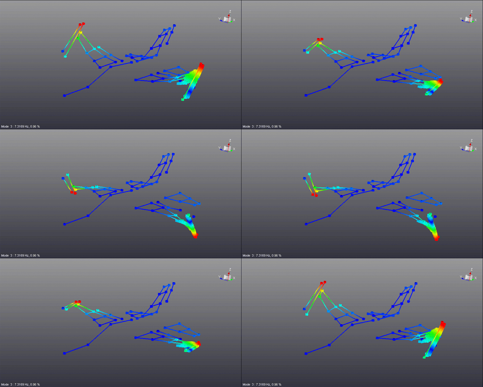
The technique has been applied here on an F16 aircraft during GVT and combined with accelerometer measurements. Global modes information of the complete aircraft obtained with accelerometers is combined with detailed DIC results on the specific parts of the structure. This allows focusing on the aircraft structure areas such as the wing tip where non-linearities might be observed.
The measurement system allows full synchronization between the digital cameras, the measured accelerometer data, and the shaker excitation signals. This enables to process of the combined data in a streamlined way. Frequency response functions and modal parameters are calculated the same way on both data sets. In that sense, the DIC technique is really complementary to the traditional accelerometer-based measurement approach.
The DIC technique does not necessarily require high-speed cameras to measure vibrations and characterize the aircraft’s modal behavior. More affordable low-speed cameras can also be used. In this case, a resampling technique is automatically applied after the measurement, which allows the extraction of vibration data at frequencies well above the cameras’ frame rate.
The DIC technique offers interesting capabilities to accelerate aerospace structures’ modal testing and get deeper insights into the structural dynamics of complete aircraft during GVT. This technique can nicely complement traditional accelerometer-based measurements and help testing teams being more efficient.
To learn more about the DIC technique, read this article.

Don’t hesitate to contact Thanh for advice on automation solutions for CAD / CAM / CAE / PLM / ERP / IT systems exclusively for SMEs.
Luu Phan Thanh (Tyler) Solutions Consultant at PLM Ecosystem Mobile +84 976 099 099
Web www.plmes.io Email tyler.luu@plmes.io

